How To Wire A Motor Starter With Overloads
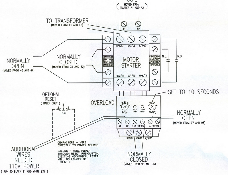
If the coil is line voltage (208, 240 or 480) then one of the incoming lines lands on the bottom contact. In the line is the same as just putting the overload before the motor as with a dol starter.
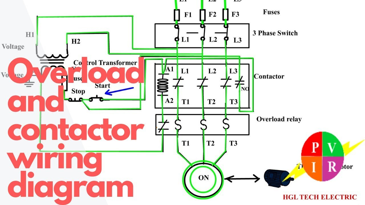
Contactor And Overload Wiring Diagram Wiring Diagram And

[automerge]1568308840 [/automerge] all other motors are 115% times the fla.

How to wire a motor starter with overloads. 240 volt, 1 phase motors should use a 2 pole starter. Circuit and overload protection for individual motor loads. Using this method the current is balanced between the 3 poles on the overload.
Dol starter control and power wiring by using a fuse, contactor, overload relay, motor. If the motor current is 22a and the rated full load current is 20a, then the load factor is 22/20 = 1.1. Like a contactor, overload protection is a building block of starters.
If an electrical ground is not located in the motor starter overload circuit, the problem has been isolated to the control circuit field wiring. How to wire up a 3 phase motor starter. This wiring should not be used on 240 volt circuits.
Allen bradley motor starter with overload protection wiring diagram 110v control. When you make use of your finger or perhaps the actual circuit with your eyes, it is easy to mistrace the circuit. How to wire a motor starter with overloads how do you calculate overload?
Mike if the service factor is 1.15 you take the fla times 125% and that’s the amperage you set your overloads. It connects the motor directly to the power supply. The motor starter must have at least two components to operate:
Please note, as this jumper wire will be carrying line power to the motor it is important the wire gage is selected based on the current load going through the contactor. Then wire the overload relay with mc. You ll be able to often rely on wiring diagram as an crucial reference that may assist you to save money and time.
Then reconnect the motor starter coil, overload circuit and field wiring, restore incoming power and start the motor. This will be the load factor for the motor. You must remove the wire, and then connect the separate control voltage lines to the number 1 terminal on the remote pilot device and terminal 96 on the overload relay.
Print the wiring diagram off plus use highlighters to trace the signal. Wire and fuse sizes are listed for reference only and may vary with type of insulation. Divide by the rated full load current from the motor nameplate.
What is the service factor. The wire that's factory connected to the top terminal goes to one side of the coil. How to wire a contactor and motor protection switch.
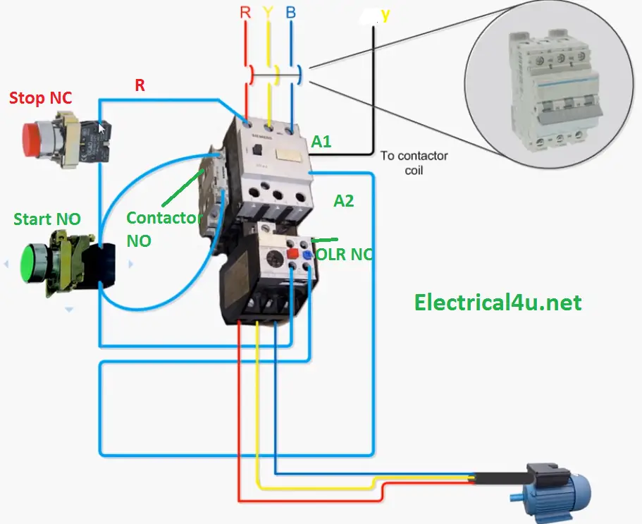
We start by bringing in the 2 power leads to l1 and l2 on the contactor. A manual motor starters diagramweb.net. Sizing for overload is important to avoid serious damage for electrical application such as motor starter,machinery or others electrical equipment.
According to nec,the general requirement for overload sizing be set around 115% or 125% from full load ampere.we should setting the overload relay within this parameter to avoid. Easy and simple wiring diagram to make you learn easily watch the vid. The simplest form of motor starter for the induction motor is the direct on line starter.
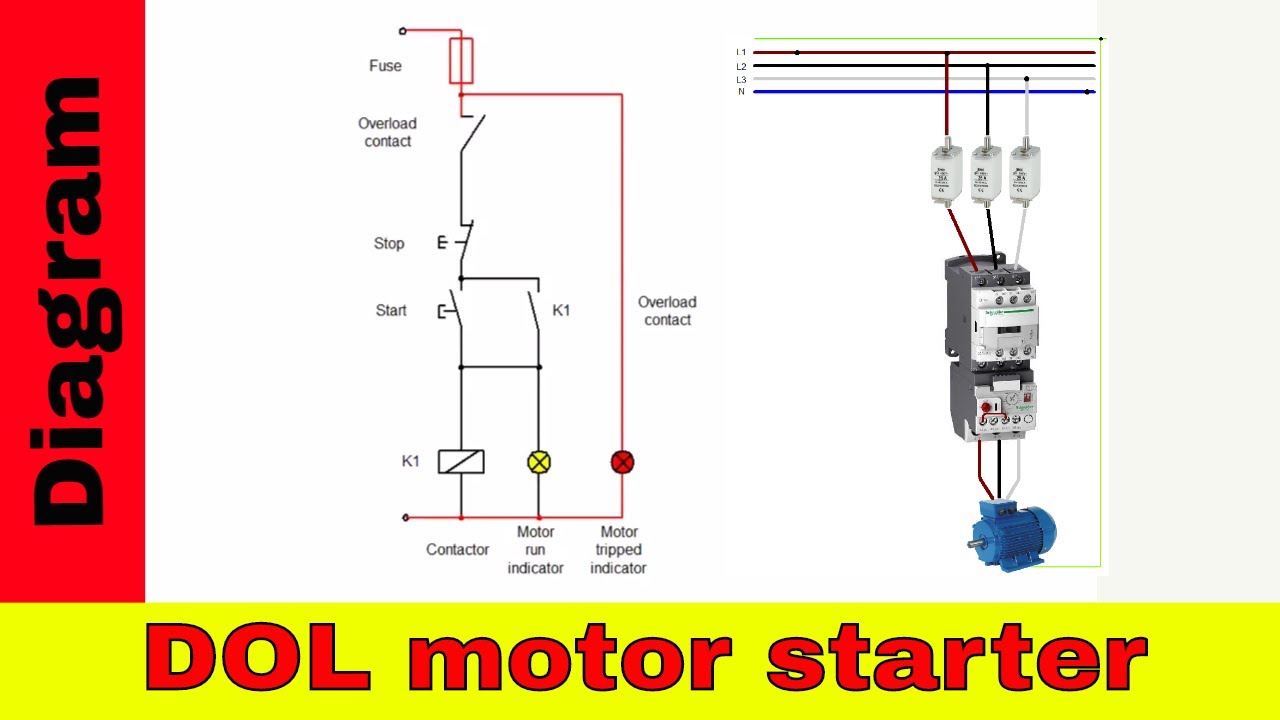
You must watch this video! This means the motor is overloaded by 10%. = + starter controller overload protection figure 6.
This directs the current through from l2 and. Overload relay motor damage 12 awg wire damage thermal withstand limit contactor breaking current contactor withstand 30i e 2 crossover point i c = 5.5 ≈i e motor start mcp (700%. This type of motor starter works on a full voltage motor starting technique.
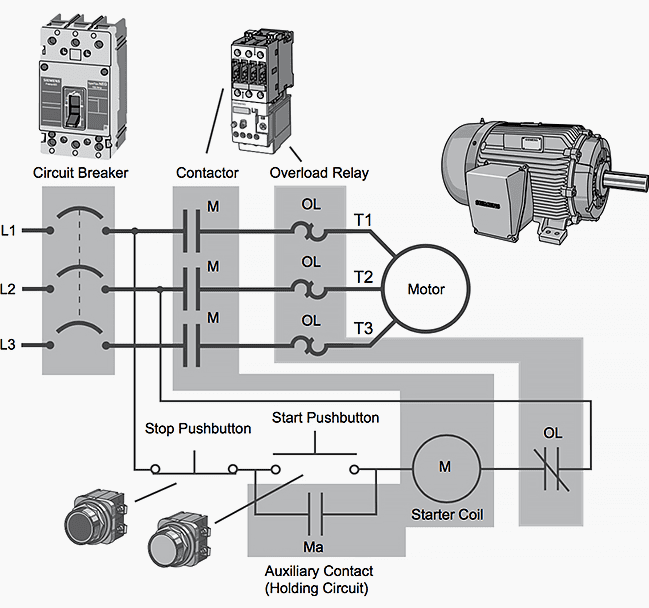
01/07/2011 by lemau 16 comments. L1 is line 1 in and should be connected to one of the hot wires, l2 is line 2 in and should be connected to the other hot wire. A contactor to open or close the flow of energy to the motor, and an overload relay to protect the motor against thermal overload.
Square d wiring diagram size 2 motor starter with overload. Then we add a jumper wire from l3 on the contactor to t2 on the overload relay. T1 and t2 are the corresponding motor out connections and should be carried through to the motor.
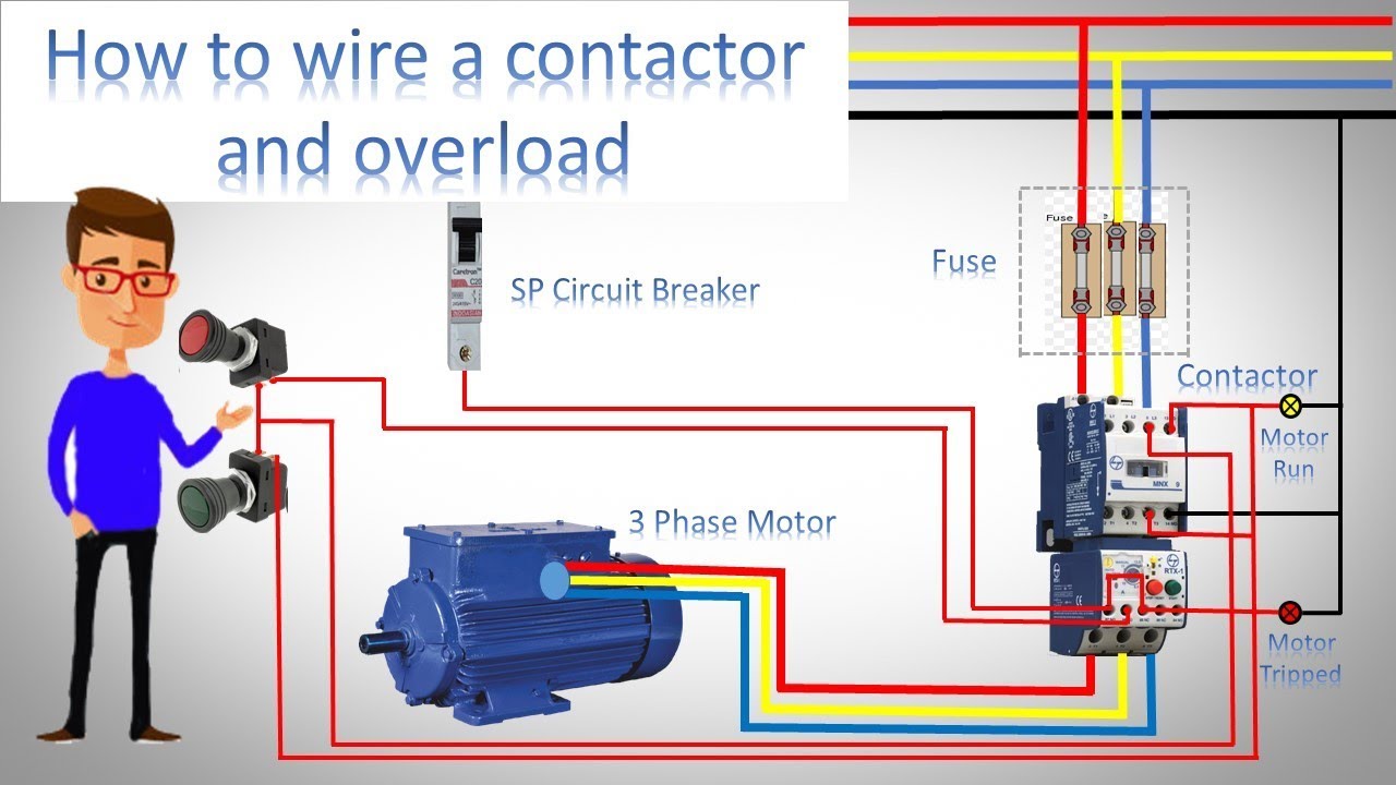
How to wire a contactor and overload ? Check the motor starter contactor, the fuses, and the overload relay. But dol starter also designed to trip the circuit or disconnect the motor from the power supply when an overload fault occurs.
Clear the ground in the field wiring circuit. Check red to blue, blue to yellow, and red to yellow phases. Motor starter protection graphic explanation.01.1 1 10 100 1,000 time in seconds 10 100 1,000 10,000 current in amperes motor circuit protector (700% fla) legend:
1 product bonitron 6 product. The main function of a dol starter is to turn on or turn off a motor. Dol motor starter with 230v contactor.
Print the wiring diagram off plus use highlighters to trace the signal. This directs the current through from l2 and directs it through the 3 rd phase on the contactor and overload l3 t3. When you make use of your finger or perhaps the actual circuit with your eyes, it is easy to.
1 trick that we 2 to printing a similar wiring plan off twice. If the coil is 120, the neutral lands on the bottom terminal (yes, starters open the neutral for overload). A starter is made up of a controller (most often a contactor) and overload protection let’s begin this section by learning how a motor works, and why overload protection is needed.
How to wire a contactor and overload Direct Online
Motor Starter With Overload Protection Wiring Diagram
Gallery Of thermal Overload Relay Wiring Diagram Sample

3 Phase Contactor Wiring Diagram Start Stop Pdf 2 pole

Motor Starter Overload Wiring Diagrams Wiring Diagram

3 Phase Contactor With Overload Wiring Diagram Wiring
DOL Starter Wiring Diagram For 3 Phase Motor Controlling

Diagram Thermal Overload Relay Symbol Electrical Wiring

3 Phase Contactor With Overload Wiring Diagram Pdf

Motor Starter With Overload Protection Wiring Diagram
Direct Online Starter Animation Diagrams Diagram

Motor Starter Overload Electrician Talk Professional

Contactor And Overload Wiring Diagram Wiring Diagram And
How to wire a contactor and overload Direct Online

Three Phase DOL Starter Wiring Diagram With MCCB Contactor

Basic PLC program for control of a threephase AC motor
Electrical 75A CONTACTOR 603200
three phase dol starter Control ! overload!Indicator and

3 Phase Contactor Wiring Diagram Start Stop Cadician's Blog