12 Valve Wiring Diagram
The valve orientation for 1.5” (38mm) There will be primary lines which are represented by l1, l2, l3, and so on.
I have a 1998 Dodge 3500 with 12v. It stalled out while idling and found the number 9 fuse

Cummins marine fuel shutoff solenoid wiring time for a class in “fuel solenoids ” 1) grab your old solenoid and get a 12v battery & some 12 awg test leads — go to your bench cut the black wire off the plug (as close to the plug as possible) and install a.
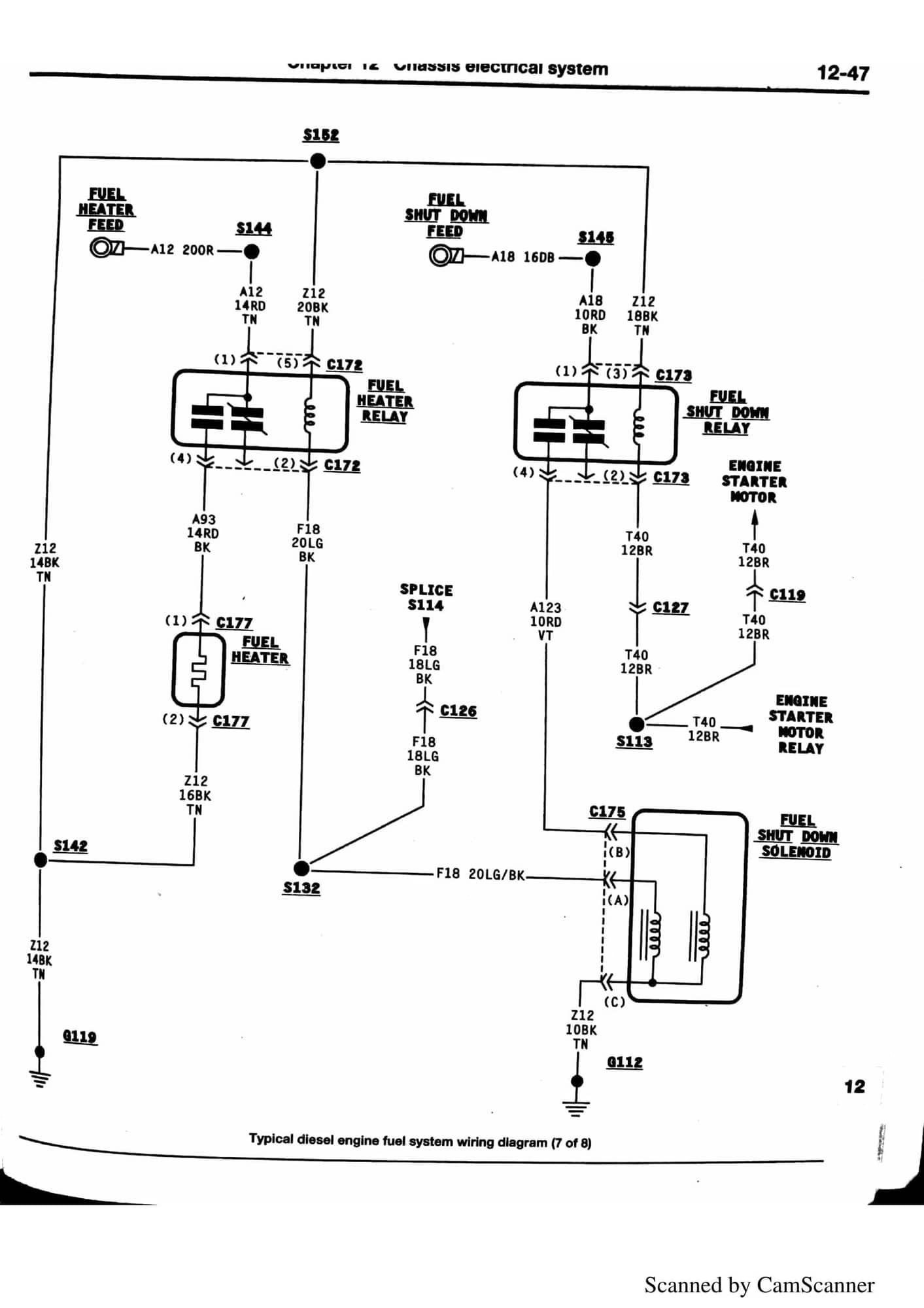
12 valve wiring diagram. Cummins marine fuel shutoff solenoid wiring time for a class in “fuel solenoids ”. You can still hear the motor running turn it off and back on and it works for approx 10 seconds, then slows down and stops. 5.9 cummins fuel shut off solenoid wiring diagram.
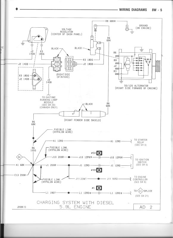
At times, the cables will cross. Here is a dodge 12v cummins engine diagram. Cr3 01 wiring diagram (3 wires control ) 1.
Symptom or problem verification to do motor not running check for power connection to dc motor check power to start solenoid G 1) have an epoxy encapsulated ascor red hat iit solenoid. Refer to pilot valve drawing for.
Vickers solenoid valve wiring diagram. Rd & gr connect with positive, bk connect with negative. Ryobi table router, slows down and stops working.
1) grab your old solenoid and get a 12v battery & some 12 awg. And the more i look at the 1997 diagram, the more i really wanna find the latest 1998 model, preferably the latest possible 12 valve with a digital odometer. Valve so the valve body remains under vacuum at all times and the pump down of the valve body is eliminated.
Caconversions, custom automatic conversions, powerstroke, ford transmission, f250, f350, e40d, ford truck, powerstroke to allison conversion, 4r100, ford diesel. Each component should be placed and linked to different parts in particular. The other wire that just holds the solenoid in place is spliced into a whole bunch of other.
Actuator automatically power off after in place, valve remains. Variety of 12 volt solenoid wiring diagram. Remove the relief valve (c) from the block, jog the unit for a second or two, until the pump builds pressure, replace the valve in the port, retorque (22nm/16 ft.pounds) the valve, restart the unit.
Asco series solenoid valves are general service, pilot operated, the series come completely. Asco redhat 2 wiring diagram. The 12 circuit harness is great because every wire is labeled every few inches so you always know which wire is which.
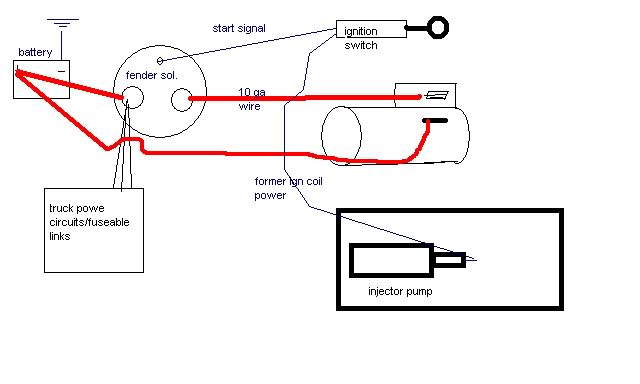
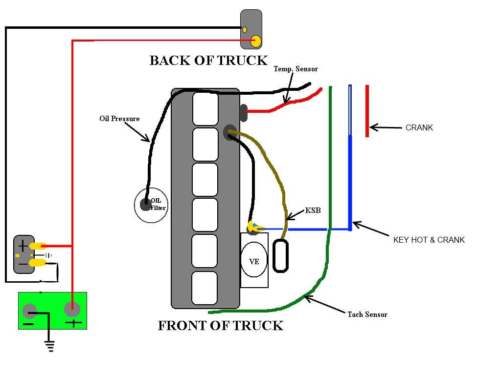
Connections to the valve are made in the wiring housing, and a ground terminal is provided. Click on the image for a larger version. Looks like it has two wires on the injector pump.
One must be for the fuel solenoid, what is the other wire for? Blue wire is a c compressor. The fuel shutoff is not getting power on startup.
Zone valve wiring diagrams boiler wiring diagrams wiring f or 4 wire zone valve low voltage 120 volts 120v 24v boiler connections t 1 t 2 3 zone valve hot neutral When close (gr) & sw connected, the valve closed, the. Injunction of two wires is usually indicated by black dot at the junction of two lines.
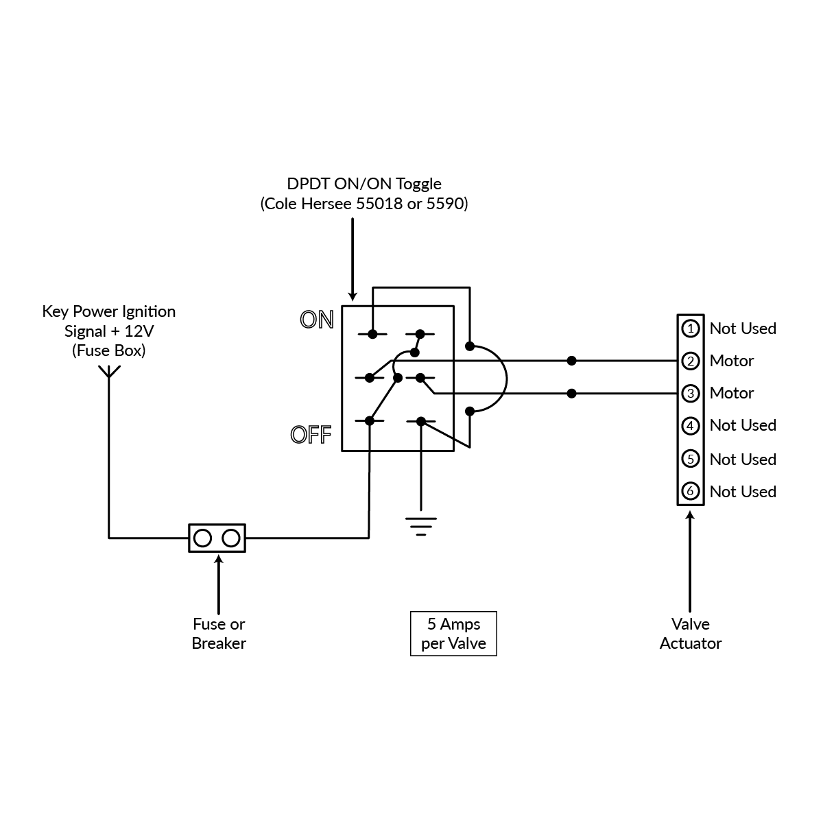
When open (rd) & sw connected, the valve open, the. A solenoid electromagnet with its core a valve body containing one or more orifices flow through an orifice is shut off or allowed by the movement of the core when the solenoid is energized or de energized. I am the lucky one that gets to do the wiring.
As stated earlier, the traces at a 12 volt winch solenoid wiring diagram represents wires. From the second column, identify the power requirement of the valve being used. 12 volt conversion wiring diagram wiring diagram is a simplified usual pictorial representation of an electrical circuit it shows the components of the circuit as simplified shapes and the skill and signal connections amongst the devices.
Both comments and trackbacks are currently closed. Solenoid models, pilot valve & cover s/a are rotated 90_ clockwise from body. Do those things start fine without the intake heater, because i am thinking about just removing it from the engine.
Wire diagram for taco zone valves. But, it does not imply connection between the wires. Unless otherwise specified at time of order, all valve cycle times and closing pressures are calculated using ‘horizontal’ (diagram 10, page 12) valve orient ation.
2001 ram 2500 qclb 4x4 auto. Wiring manual pdf 12 volt eton solenoid wiring diagram.
12v Hydraulic Power Pack Wiring Diagram Sample
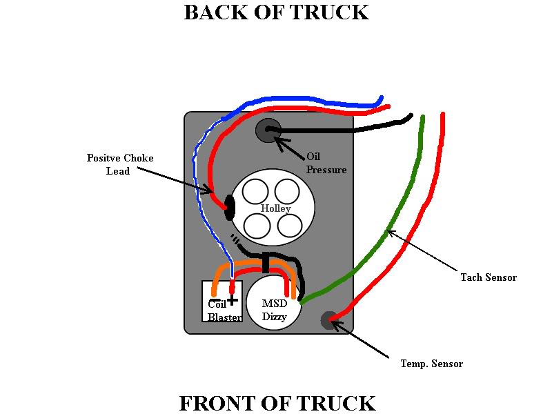
1987 Ford 12 Valve Cummins conversion Page 4 Diesel Bombers
12 Valve Cummins Fuel System Diagram General Wiring Diagram

1987 Ford 12 Valve Cummins conversion Diesel Bombers
Buy Grooved Butterfly Valve (12V Electric) online at Access Truck Parts
12v Hydraulic Power Pack Wiring Diagram Sample

1987 Ford 12 Valve Cummins conversion Diesel Bombers
Automotive Toggle Switch Wiring Most 12 Volt Toggle Switch Wiring Diagrams Pump With, Way Valve

311006 12v Solenoid Wiring Diagram
How do I Connect a Pump Relay Master Valve to my RainMachine? RainMachine

jmw642 Dodge Diesel Diesel Truck Resource Forums
12 Valve Cummins Alternator Wiring Diagram Database Wiring Diagram Sample
28 12 Valve Cummins Fuel System Diagram Wire Diagram Source Information
12v Hydraulic Power Pack Wiring Diagram Download

1987 Ford 12 Valve Cummins conversion Diesel Bombers
12 Valve Cummins Fuel System Diagram General Wiring Diagram

I need a wiring diagram for the selector switch on my 9345 Belarus. Only getting 12 volt to the

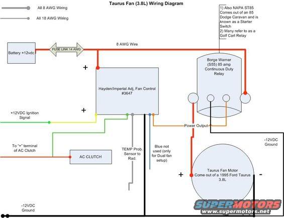
Cummins 12 valve electric fan install write up Diesel Bombers
12v Hydraulic Power Pack Wiring Diagram Sample
